To the IMAX Moon and Beyond
We didn’t have their giant rockets, so we faked it later.
On September 23, 2005, Magnificent Desolation: Walking on the Moon in 3D released on giant IMAX screens. It is a 4K stereo3D experience of the moon landings, and speculative missions from the past and future. The film was honored with the first Visual Effects: Special Venue award by the Visual Effects Society in 2006. This multi-part article is based on a presentation about the visual effects at LA SIGGRAPH, the following June.
Here is an overview of the work:
Part 1: Prep and Landing —Preparing for Stereo3D in 2005 and Beyond.
Part 2: Strolling on the Moon — Stereo3D Methodology, and Innovations.
Part 3: Touchdown — Moon Landing Simulation by John Knoll.
Part 4: Flight Time — The Lunar Flight Simulator of Paul Fjeld.
Magnificent Desolation: Lunar Excursion Sequences
Part 2: Strolling on the Moon
The previous section covered photography and stereo pipeline setup for Magnificent Desolation at Sassoon Film Design (SFD). Significant amounts of image processing and new color methods prepared tens of thousands of frames for the next step — actually building the visual effects sequences at the company, which we cover here.
Stereo Compositing for IMAX3D
Matte Extraction:
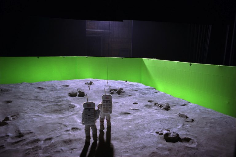
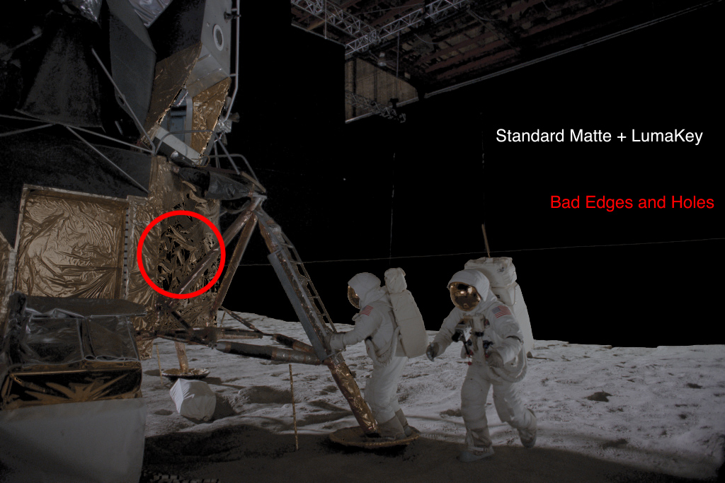
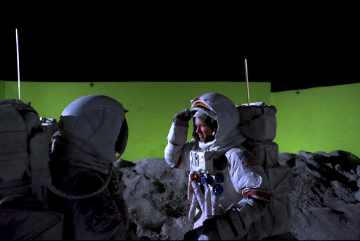
The actors must be isolated from the photography to replace their background with lunar images, so the production went to great expense erecting a 20 foot green screen around giant stage 27 on the Sony Studios lot for that exact purpose. Unfortunately, the wire suspended astronaut/actors were easily 30% over the black stage background, and only partially covered by green screen. The on-set lighting was harsh, to simulate actual conditions, but luckily enough bounce light from the ground illuminated them to make their shadows a dark grey, rather than harsh black. This short screen and harsh lighting was far from ideal for the visual effects crew, and the matte extraction task fraught with difficulty because of it.
The standard method to extract foreground features from a non-process screen background is called rotoscoping, in which an artist painstakingly traces the silhouette of the image for every frame to build an extraction matte. In this instance it was never seriously considered, as doing so in stereo IMAX would have crippled the entire production. Stereo rotoscope is one of the most difficult tasks in a 3D film, even with current tools — let alone those available in 2005. If an edge is not properly traced for both images, to exactly follow the contour, it is possible that the edge of a character will have a unique stereo3D depth, and will float in front of the feature on a 3D screen, creating a stereo anomaly. Out of necessity there would be some rotoscope in the film, but it was best to keep it at a minimum.
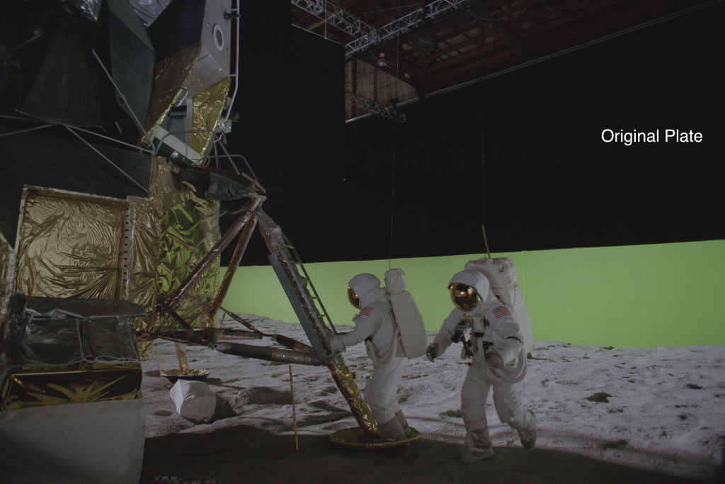
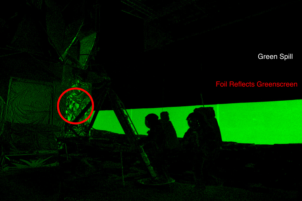
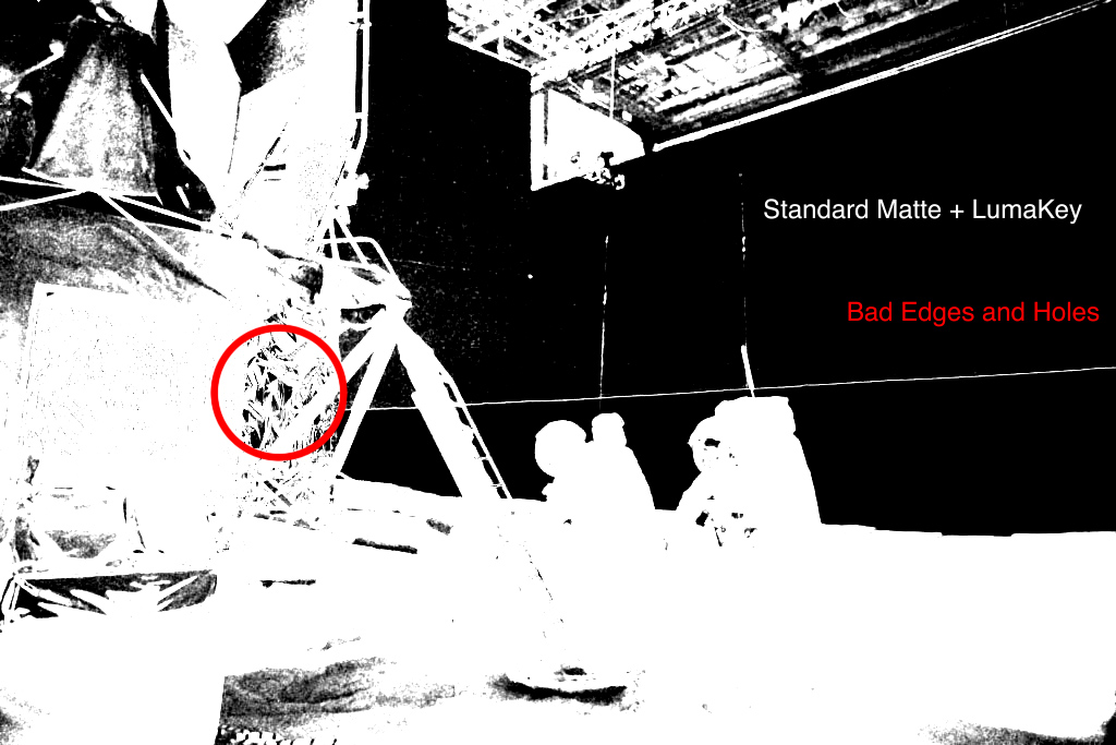
There were more complications with matte extraction than the black background. The green screen was slightly over-exposed, and conversely the black stage was under exposed. The brightness of the screen was “blooming” around the actors, and the ultra white helmets did the same over the black stage. Early tests for matte extraction revealed that the silhouette was alternately thick and thin depending on how much crossover there was. That aside, the very shallow focus of the lenses (not something you typically associate with lunar photography), and the plethora of gold foil on the LM and reflective helmets further complicated the process. If you consider that the photographed green screen was actually closer to yellow, than green — It would not surprise anyone that every matte extraction tool failed to get clean mattes, and combining multiple methods still did not resolve the odd reflection, or alternating matte thickness.
It seemed that nothing was going to be easy.
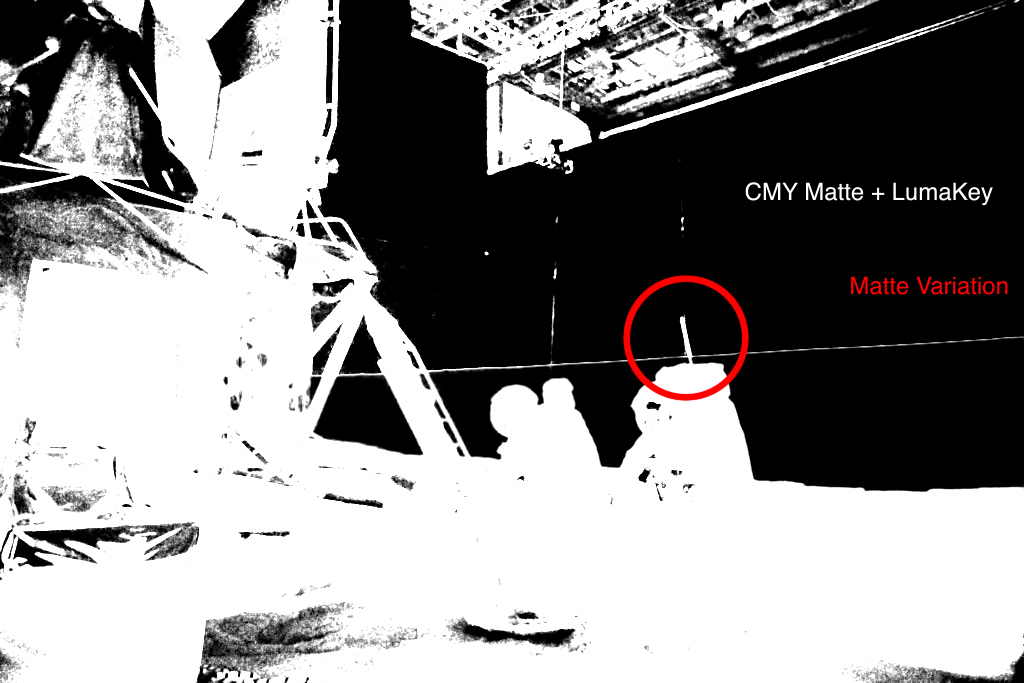
To solve this complex matting problem, the team used a technique based on subtractive color CMY reductions, normally used for offset printing, which successfully identified the green/yellow screen cleanly, and pulled clean edges for props and helmets covered in gold foil. A second luminance map removed the dark areas of the shot, and the two then combined. Remaining holes were easily patched with rotoscope shapes inside the silhouettes, as the edges were all identified. With only the scaffolding and wires remaining, another simple rotoscope quickly completed the extraction matte.
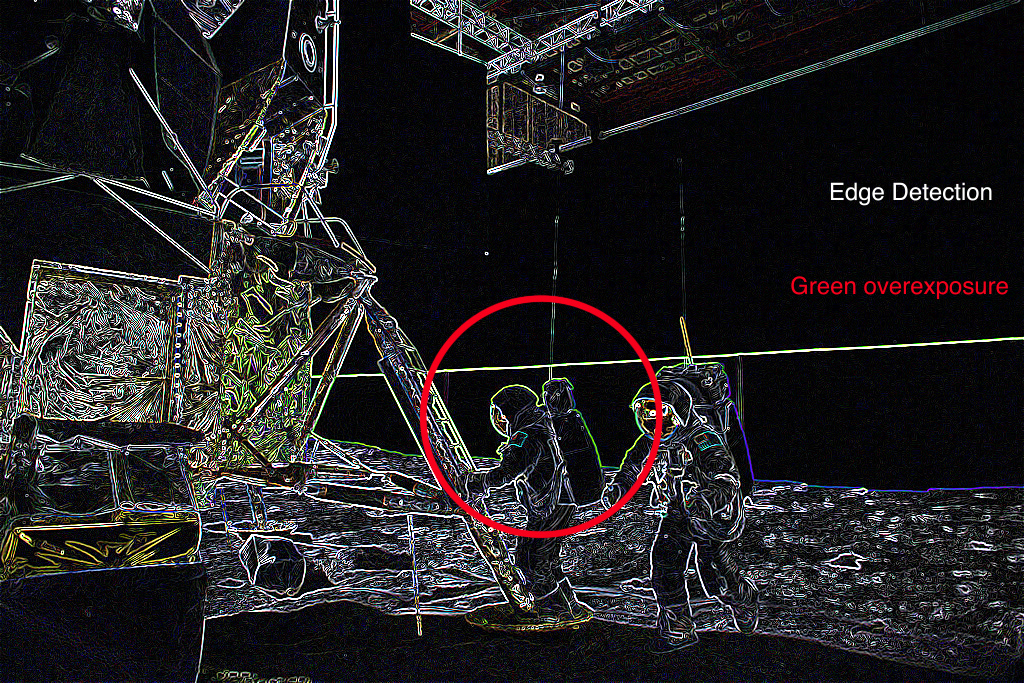

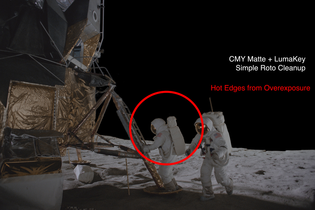
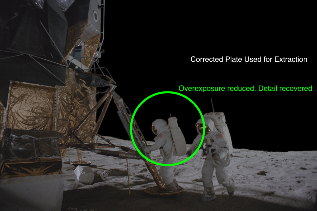
The CMY method did not fix the problem with the edge thickness differences between black and green. It would be necessary to clamp the exposure on the white parts of the helmet over black, and clamp the overexposed green screen. This was accomplished with a “find-edges” filter, which easily revealed the scale, and intensity of the overexposed edges. This edge detection was multiplied at 50% over the original image. It effectively brought the exposure down on the overexposed edges, and normalized the astronaut silhouette. A simple core matte was used to re-introduce original imagery inside the body of the actor to create a new source image and the CMY matte extraction followed. The overall procedure saved hundreds of hours of exacting rotoscope work, and helped the team all to realize that, in good NASA tradition, they could think their way out of a challenge.
Composite Workflow:
Compositing stereo IMAX films is challenging to say the least. Due to memory requirements in 2005, it was unwise to combine too many compositing processes together at one time. A node-like structure comprising networked singular solutions handled computer memory and processor cycles more efficiently. Adobe After Effects, the main compositing software, is a mostly layer-based compositor, which allows artists to keep stacking processes ad infinitum — or until they run out of RAM. Whenever a process can be pre-composed, it reduces the memory requirements to store that image, supplying that now free computer memory to the next step. By handing off one element process to a single frame buffer by pre-compositing, the memory requirements for the shots were easily managed. On the average, the composites for Magnificent Desolation completed in less than 7 minutes a frame on single processor computers, and that was due to proper management of process, which is why common composite structure from the layout department was so important at the beginning.
The other challenge with stereo compositing is that the exact same process has to happen to both composites, but only slightly to the left. There were no single compositing pipelines that split into two outputs, as there are today, instead each entire composite structure was made twice. Typically the work was finished on the prime (right) eye images, that structure duplicated, the elements for the second eye swapped in, and any adjustments made from there. Careful control of naming conventions was critical to making this process as swift as possible.
Paint and Repair:
For the most part stereo3D work to remove unwanted scaffolding, or wires was part of rotoscoping, but on occasion the offending feature would be over the front of an actor, or other important object like the Lunar Module. Typically this is the realm of digital paint and fix, which begs, borrows, and steals pixels from surrounding frames, or nearby regions to repair the imagery. This is of course a recipe for disaster if you have to do that kind of work exactly the same for the other eye, but also slightly in depth. Wherever possible, procedural methods were used to replace portions of frames, but invariably there was a shot that required manual paint work.
A few years earlier, for an NFL promotional piece, in which the stereo cameras had mismatching focal distances, Sassoon Film Design used optical flow based stereo disparity of the two images to warp portions of footage that were in focus to the opposite eye, resulting in an image that was a hodgepodge of different regions of both pictures. This technique, though typical today was unique at the time, and re-implemented for Magnificent Desolation. The paint work would be done on one eye, and warped with optical flow tools to its twin.
There were also instances where astronauts should leave footprints on the surface, and those needed to be painted on as well. Although covered in dust, there was not as much of it on set as there is on the Moon. The dust on the surface of the set was minimized as the shooting continued, as it was being kicked up by all the activity, and floated in the air (which there is none of on the moon). Thus it became a nuisance, and no one left footprints on the surface after that, unless they were painted in by the visual effects team. Special brushes of astronaut footprints were made in Adobe Photoshop, stamped all around the scene, and the aforementioned disparity warping tricks used to seat the matte painting to the set.
3D tracking — Camera and Props
Rock and Roll Tracking:
It is nearly impossible to build virtual sets for anything in stereo3D, unless you know where the camera is. Luckily, the film production used an encoded pan/tilt head on the camera platform to record camera data, but unfortunately it was not a fully encoded system, and therefore was only useful for a few shots. To resolve camera positions, we turned to the relatively new 3D tracking package Syntheyes, by Andersson Technologies. It is a very robust tracking engine that resolves both cameras and moving objects — which was fairly unique at the time, (especially at its very affordable price point). SynthEyes was capable of tracking full resolution 4K shots, but to maximize speed and avoid RAM issues, 2K and 1K resolutions were the workhorse for most tracking. The resolved cameras tracked at that resolution were surprisingly accurate, and rarely required the 4K plates.
Like all other 3D tracking software in 2005, Syntheyes did not have any way to solve stereo3D cameras. The standard practice even today is to track the camera for the least distorted image, and then add the inter-ocular distance and lens convergence to a duplicate camera slaved to the solved. Theoretically this makes perfect sense, but in practice does not produce an accurate 3D camera that matches photography. The cameras can only be reasonably lined up, and the differences between them is more than distance — there are just far too many variables to control. Tracking each camera individually also would not suffice, as at that time there were no cross-links between the camera systems that could constrain them to a stereo3D camera setup. [as an aside, Sytheyes is now fully stereo3D capable]
The object tracking ability in Syntheyes was critical to the production, as SFD was responsible for replacing the Astronauts visor, and reflections. Visor tracking had to be perfectly accurate, because any misalignment in depth would reveal the illusion. Each scene needed to be properly scaled to match the size of the set and props, and placed at the proper distance to marry the footage. Most of the shots had no scale reference other than the astronaut’s helmet (the rocks were moved between shots), but that was not enough to determine the placement in stereo3D very easily.
The solution for both problems was unique. The frames in the left-eye plate were reversed in time, appended to the end of the right-eye frames, and both shots tracked as one continuous sequence. At the point where the images changed from right to left-eye, the solved camera would make a single-frame jump. This ‘inter-ocular distance’ was then reconciled to the known measurement from notes provided by production (normally 2.5 inches), and the whole solution scaled to match. Upon export, the resulting camera move would be split, and reversed on the left eye once the proper scale was determined. The helmet or other objects could then be tracked into the scene at the right size and depth.
Prop tracking:
For shots of the lunar rover driving across the surface, the bouncy, frail communications antenna sat precisely on the problematic edge of the green screen, and black stage mentioned earlier. Due to the thin features on this prop, it was determined that completely replacing it was a better idea. The object was tracked in Syntheyes and rendered out as a 3D object for problematic scenes — which was most of them. The tires of the rovers were also individually tracked, as they moved independently across the surface.
Myriad other objects held by the Astronauts were also tracked based on the need of the scenes, often just to rebuild reflections. Occasionally the feet of the astronauts, their individual steps, were 3D tracked and keyframe animated by plotting an intersection curve from the camera point of view on the geometry recovered from the set during tracking.
All data from the 3D tracking was exported from Syntheyes to After effects, Maya, and Electric Image Animation System using custom Sizzle, Javascript and Mel code — establishing a common 3D space. This tool existed in each software package and allowed for any 2D or 3D solution to be shared between the applications bi-directionally, essentially merging the multiple projects into a single unified 3D environment.
Building the Visors:
The prop house did not want their helmet 3D scanned, so the it was recreated as a 3D model by using Syntheyes as a simple photogrammetry engine. Still shots of the helmet with tape marks on the visor were tracked as a continuous shot, a model built of the few resulting points by manual silhouette matching. The internal pressure bubble was modeled manually from historical reference.
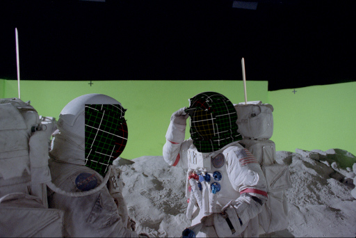
Despite the effort to make final 3D tracks of these props 100% solid, there would invariably be minor irregularities with the helmet position. The general perspective and motion were accurate, but the visor might have a high-frequency wiggle from frame noise, or it could be floating in 3D depth in front of the faceplate region. This required a refinement step in compositing, in which an artist would reposition both Left and Right elements to remove jiggle, and then further adjust them to fit properly in-depth. To reduce error from manual positioning, a 2D motion curve extracted from the 3D helmet tracking, stabilized the footage around the visor, and the image cropped to fit. Using the custom data exchange tools, a stabilization curve, and render resolution were sent back to maya, or Electric Image to modify some position and rotation parameters, and render the 3D object in lighting. Once the artist was finished tightening the motion in this stable composite, the same motion curve was used to reposition the result to remove all the tracking issues. The smaller frame size of stabilized renders had an added benefit of rendering faster, and reducing memory requirements as well.
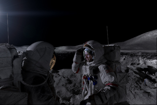
Wherever possible, reflections from the actual photography on visors would be maintained, as long as they did not reveal camera crew or stage, but these reflections were incomplete, and at times almost entirely obscured by tape which hid a lot of the unwanted reflection, or acted as tracking markers. The tracking markers were removed by procedurally shrinking in the pixel color around the markers, and hiding the resulting blurry area behind a rendered smudge of dirt on the visor. Any additional reflections would be recreated in CGI and rendered as a stereo3D set of images, which also had to reflect every other visor visible in the shot.
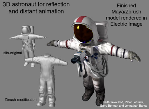 For the reflections, and distant animations of the Astronauts, a model was very roughly built in NerveCenter’s Silo software, based on tracked stills of the actor rotating around every 45 degrees with his arms outstretched. This model was refined in Pixologic zBrush (which was a new tool at the time), and tracked photography projected back on to the surface to recover a texture. The helmet model built previously was then placed on top, and the whole character rigged for animation.
Much of the local stereo reflections were replaced with full 3D character animation, essentially TRIPLING the workload for stereo reflection — per astronaut. Three team member spent most of the production cycle animating and fitting all of the visors and pressure bubbles into the shots.
Any shot of the Astronaut point of view was also a fully rendered CGI prop, as it was necessary to replicate the lighting on the helmet. This personalized view was a significant departure of any other IMAX film at the time, as it was considered a violation of the “rules” set down by prior stereo cinematography( Which this film broke repeatedly, and on purpose). It was not possible to get the camera system inside any real helmet, due to its size. For these point of view shots to work, it would require a lot of finesse on the filmmakers part, and this allowed them to work out the difficulties in post production.
Terrain Photogrammetry
The original test that helped green light the film was created by manually modeling the surface of the Moon by hand, devolving the image by analyzing the perspective, and at times making it up as a best guess. For the final film, the approach needed to be far more accurate. There was no Digital Elevation Model of the Moon publicly available at the resolution we needed, so multiple shots from the historical archive were 3D tracked to solve camera positions all over the landing sites. The resulting solved cameras and points were used as a basis for modeling. (More on this procedure is published in the VFX Touchstones: Part One.)
The photogrammetry based models were the core for all the distant terrains, and color balanced, cleaned photos from the Apollo missions were projected from the camera positions as a texture. A similar process was used to recover the geometry of the set, by rebuilding it from tracked stereo3D photography. These two terrains were then connected with a joining piece of geometry, and the gap filled-in with a 3D digital matte painting that blended the two sets of images.
Probably the most effective portion of this photogrammetry was a ground-level view of Hadley Rille. This enormous canyon is awe inspiring, and unfortunately only partially visible from the photographed areas. The far side and surrounding hills were put together out of photogrammetry of three different locations that were miles apart, as they provided enough parallax to resolve the geometry at that scale. The near side photography was built from the set — shown in a dramatic arcing camera move over the edge of the rille — which was extended with rocks and debris inspired by the photographs. The rocks were modeled in zBrush.
For the big pullback along the ravine all the way to the last area the Astronauts photographed, the recovered geometry from SFD was used as a basis to build a larger terrain by Eric Hanson and his team at xRez studio, who expanded on the geometry and built a majority of the texture maps based on surrounding photography. The shot was designed to drop back into the SFD workflow at the end.
“There was one shot in particular that required a fairly large amount of photogrammetry and camera-projection work, and that was flying through this deep trench called the Hadley Rille. It’s one of the more spatially interesting shots in the film. Sassoon contracted us to do that shot development, lay that all out, and get the texturing and matte-painting done. Actually, NASA allowed us to scan the original Hasselblad imagery from Apollo 15, so we had some very high-resolution images. Luckily, at that time [1971] the astronauts were savvy enough to take a series of rotational images, kind of doing panoramic acquisition there on the moon. Of course, there was no stitching software back then so I’m not sure if they ever really did put them together, but it provided a great base for us. We took certain locations surrounding this trench where they shot these overlapped images and digitally stitched them together, and from there we were able to use photogrammetry techniques to derive the actual shape and geometry of the trench. Once we had that, we established a camera path and created 24 separate matte paintings – overlapping textures and paintings – derived from the imagery but extended to create the shot. This was all rendered in stereo, as well, at IMAX resolution. It was a pretty fun shot.” – Eric Hanson interview from StudioDaily
The above video shows the status of the shot delivered to SFD by the team at xRez. It was easily the largest scene in the entire film, ending with scale reference of the Statue of Liberty. The artist primarily responsible for the work later joined the team at SFD to help complete the shot. Initially laid-out in [Autodesk] Maya, all the geometry, cameras, and texture maps were moved over to Electric Image using the proprietary data exchange tool. Electric Image was chosen because camera projection, and large geometry were processed more efficiently, reducing render times. Matte paintings were enhanced based on the notes from production, and blended back into the setup. The final shot (seen below in context) was rendered, and then composited in Adobe After Effects in stereo3D. The astronauts were also 3D tracked from their footage, and stabilized on two 3D cards to fit in the scene. All of the work for their visors and green screen extraction were completed in prior steps.
Here is the final shot in context at low resolution. To see a higher quality version, though time-remapped, please refer to the overview reel at the top of the page.
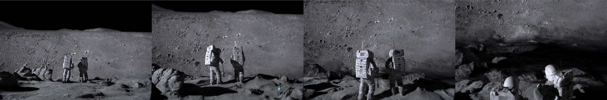
Magnificent Desolation is more than just a depiction of actual Moon landings, it also contains a fictional sequence depicting emergency plans that NASA had in place. For these sequences, the editorial team grabbed cool looking lunar photos, and roughly composited them behind the photography. The production looked at these shots for months, and were accustomed to the general layout of the mountains in the background. It was left to the team at SFD to work out the details of new lunar landscapes based on this imagery.
To recreate this fictional portion of lunar landscape, the team first laid-out the actual journey implied by the footage. After 3D tracking all of the shots, the direction of shadows revealed the position of the sun (located with the Syntheyes software), and each one lined up to that direction. The scenes were then spread out along that solar vector, and an overall U-shaped path around a mountain range led them to a nearby crater — where their lunar rover breaks down. Each of the high-resolution photos from the Lunar missions were then set up in the camera, and models made to match them. Surrounding rocks were built in zBrush, and scattered along the middle-ground terrain. zBrush was used to finish any terrain that was not explicitly from the set.
Rather than project imagery directly on the geometry in this sequence, much of the terrain was lit and rendered as a basis for matte painting. Due to the dusty nature of the surface, an Oren-Nayer reflectance model was used, which predicts surface reflectance from rough diffuse objects, and looks more like the original lunar images. The Clementine space probe had recently returned more imagery of the Lunar pole, and NASA published a depth map DEM of that region. That image was the basis for the craters on the surface of the terrain, and was stamped around at various scales in overlapping patterns. The renders from this process were then augmented in Adobe Photoshop with portions of the original Lunar material, and blended with the set photography as before.
One shot of the actors walking past the mountain, to return to their spacecraft, was initially rejected by the director, as he said he could see the seam of the set and the join to digital terrain on the large 3D IMAX screen. The VFX supervisor on the show pointed out that the seam was actually a lot closer, was completely invisible within the shot, and the line he saw was inferred by rolling hills. The final shot was then quickly approved, much to the ease of the SFD team.
Dust and Flares to Finish
Dust Simulation:
In 1/6 gravity, dust falls like lead pellets with no air resistance. Any waft of dust on the set completely blew the “reality” of our Lunar scenes, so the dust initially placed all over the set was significantly reduced. The plan was then to augment the shots with computer-generated dust particle elements. Due to the constraints of the production schedule, it was not possible to do this on every shot, as resources wore thin.
“We analyzed original moon footage [shot at 12fps] and stretched it to 24fps to understand how long the hang time was, so to speak. We then created a 3D model of an astronaut’s feet, and had our artists match-move it to the actor onscreen. A volumetric particle system was used to render the imagery, but in some cases, we used hardware rendering for efficiency’s sake. The Electric Image Animation system [from EI Technology Group] was our main rendering engine for hard-surfaced objects and environments, and [Autodesk] Maya rendered particles. By splitting rendering packages, it helped minimize the need to further expand our render farm.” – Johnathan Banta, SFD CGI supervisor
The dust system for the lunar rover was particularly interesting, as the tires are made of wire mesh. The dust therefore has the tendency to cling to the tires and get thrown up at a steeper raking angle, than one would experience on Earth. To accomplish this, a circular section was scaled along the radius of the tire based on a procedural noise function, and the movement of the actual prop — shot in slow motion. This section emitted tens of thousands of particles into the environment, which then followed a ballistic trajectory to the recreated terrain, and disappeared. It took several attempts to replicate the motion in the actual footage, and it was later realized that the fenders over the wheels were the other factor in the distinctive look of the dust plumes.
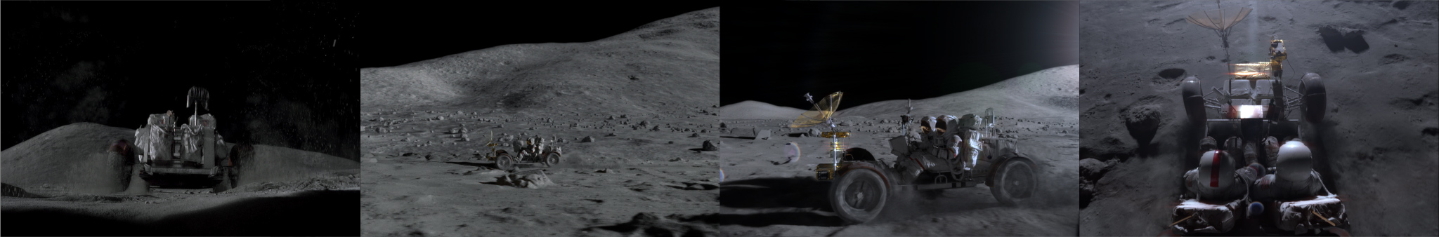
Stereo3D rendering of all particle systems was difficult, but more so on the rover due to the volume of particles required. It was necessary to cache all the particles, and render from that cache to reduce time, and create the exact dust trail for both cameras. Any difference between the two renders would break the illusion of the dust in the scene. For some distant shots, a particle system inside the compositing package was sufficient for dust interaction. Often their resulting footstep on the surface was painted in, and warped to fit the stereo render as mentioned before.
Lens Flares and Color:
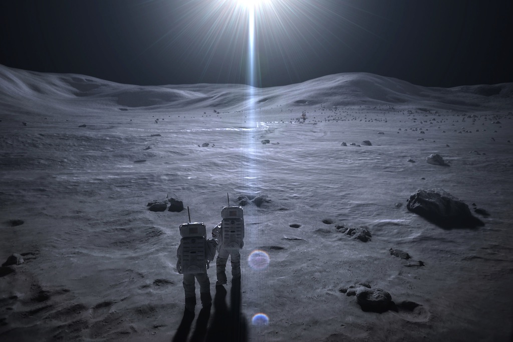
You can probably find no more high contrast images than those from outer space, and much of the Lunar photography artifacts of the 20th Century were perfect tools to minimize stereo3D issues that high contrast introduces. High contrast images cause a lot of crosstalk, or image pollution from one eye to the other, which can break the 3D illusion. To overcome this, the filmmakers chose to embrace ubiquitous artifacts in the Lunar photography and minimize the issue. Firstly, the extreme brightness on the Moon created an overall blooming to the edge of any light area, softening its exposure over dark zones. Similarly, the photography contained a “bloomed” deep black, which allowed the contrast to soften the other direction in the darkest corners. For areas with lots of black sky, and white suited Astronauts, large lens flares provided a soft gradient that flattened the image contrast as well.
The lens flare was particularly difficult to match to the original Hasselblad camera, and in stereo3D. John Knoll provided a preset for his own lens flare tool to SFD that was nearly a perfect match to the original. The lens flares were blended and art directed with a radial gradient to finish. Unfortunately, lens flares are not naturally dimensional as one would expect. When photographed, they either sink into the scene or remain flat. To solve the problem, each lens flare was rendered, swapped left to right, and repositioned back to its source. Each lens flare now reached out of the screen, reenforcing expectations of the audience, and delivering a deeper 3D experience.
Once all the elements were put together, an overall color correction was added that matched the photography of the actual moon landings — emulating the manner in which different color channels mixed on film stocks of the 1960s and 1970s. A 70 mm grain stock was composited over the top to complete the resolution up-res that began at scanning, and to replace the film grain that was removed in the image processing steps. Color variations were printed on 15-perf 70 mm film (called “wedges”) and final color tested with various filters on a light table.
Titles:
The SFD team also built the main title for the film, and a large mosaic deconstruction of the Moon illustrating the effort by all the original technicians that made the moon landing possible. The mosaic — a combination of several hundred photographs of Lunar missions — was put together procedurally, and then literally blown apart in reverse by the same software tool in Electric Image used to destroy Los Angeles for the film Terminator 2. Specific cards were eliminated from the simulation, and were animated by hand to illustrate a few specific events the filmmakers wanted to emphasize. A more complex effect that turns into a giant Astronaut at the end of the film was accomplished by other vendors.
The stereo3D logo was filled with the standard spectacular lens flares and God Rays present in many motion graphics from that time period, though avoids appearing dated. Rather than use off-the-shelf tools for the God Ray effect, which do not work properly in stereo3D, a custom Electric Image shader was repurposed from earlier work. The shader used a fractal noise pattern to create detail over a gradient ramp which extended along the depth of a 3D logo outline. This shader was develop over the previous years to create title sequences for multiple IMAX theaters, and look like 1970’s streak photography popularized after 2001: A Space Odyssey. The geometry outline was scaled to represent the light path, overtake the camera, and then rendered in stereo3D to complete the effect. The lens flares were added in compositing as stated earlier.
SFD concludes
The Sassoon Film Design team produced an incredible amount of work in the shortest period of time for any of the vendors. (Easily with half the time, and one-quarter the crew of other facilities on the show.) Despite this, several innovations in stereo filmmaking came about from the project that are now considered industry standard — especially since many sci-fi movies have covered similar subject matter with larger budgets. The team had several artists steeped in stereo filmmaking, and many new artists on their first stereo3D film. The sacrifice of the team was apparent, as there was a constant feeling that we were making something important. To this day it is still a subject of conversation whenever the team gets together as it represents one of their best works.
At the end of the LA SIGGRAPH presentation of the SFD work, during the question and answer period, someone asked “Were you not allowed to scan the helmet because NASA didn’t want you to find out their equipment was fake, and that the Moon landers were a fraud?” (or something to that effect — it’s been 10 years). Johnathan Banta responded:
“There is no doubt in my mind that men walked on the Moon, and that this is all real. The detail is too incredible. Even with today’s modern technology (of 2005), We were sorely challenged to match the quality of imagery that actually being on the moon provides,” adding “Our hats are off to the crews that actually walked on the moon. They think big.”
AG
Section 3: Touchdown – with John Knoll
Pingback: How We Faked The Moon Landing: Part 3 — The Visual Effects of Magnificent Desolation - AGRAPHA Productions
Pingback: How We Faked The Moon Landing: Part 1 — the Visual Effects of Magnificent Desolation 3D - AGRAPHA Productions
Pingback: How We Faked The Moon Landing: Part 4 — The Visual Effects of Magnificent Desolation - AGRAPHA Productions